
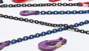
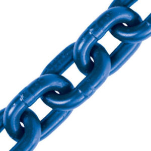
Grade ‘T’ 8 Chain
Chains and Fittings
Grade T (8) Alloy Steel Chain is manufactured specifically for use in chain slings for lifting purposes.
Similarly, The chain is heat treated for tensile strength and resistance to wear whilst also allowing for shock absorption. see all services
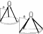
| A mm | B mm | C mm | WILL Tonnes | Kgs per meter |
|---|---|---|---|---|
| 7 | 21 | 25.9 | 1.5 | 1.1 |
| 8 | 24 | 29.6 | 2.0 | 1.5 |
| 10 | 30 | 37.0 | 3.15 | 2.2 |
| 13 | 39 | 48.1 | 5.3 | 3.8 |
| 16 | 48 | 59.2 | 8.0 | 5.8 |
| 20 | 60 | 74.0 | 12.5 | 9.1 |
| 22 | 66 | 81.4 | 15.0 | 11.0 |
| 26 | 78 | 96.2 | 21.2 | 15.3 |
| 32 | 96 | 118.0 | 31.5 | 23.2 |
Properties:
Chains and Fittings
Working Load Limited (W.L.L.) is the maximum load which chain or components are designed to sustain in lifting use. The mean stress at this load is 200n/mm2 (MPA) and is based on a factor of safety of 4:1 .
Master Links |
|
||||||||||||||||||||||||||||||||||||||||||||||||||||||||||||||||||||||||||||||||||||||||||||||||||||||||||||||
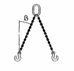
Quad Assemblies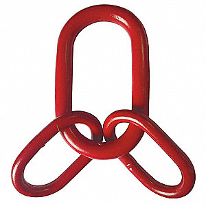 |
|
||||||||||||||||||||||||||||||||||||||||||||||||||||||||||||||||||||||||||||||||||||||||||||||||||||||||||||||
Component Connector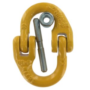 |
|
||||||||||||||||||||||||||||||||||||||||||||||||||||||||||||||||||||||||||||||||||||||||||||||||||||||||||||||
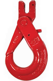
Clevis Self Locking Hook |
|
||||||||||||||||||||||||||||||||||||||||||||||||||||||||||||||||||||||||||||||||||||||||||||||||||||||||||||||
Eye Self Locking Hook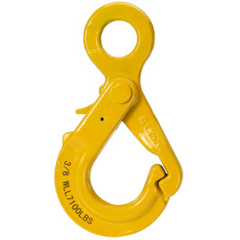 |
|
||||||||||||||||||||||||||||||||||||||||||||||||||||||||||||||||||||||||||||||||||||||||||||||||||||||||||||||
Working Load Limits
Uniform Load Method of Rating
All general purpose slings should be rated by the uniform load method as shown in the table below
| Chain Size mm |
Single Leg | Endless | 0°-45° | Two Leg 45°-60° |
Three and Four Leg
0°-45° 45°-60° |
|
|---|---|---|---|---|---|---|
 |
|
 |
 |
|||
| 7 | 1.5 | 2.5 | 2.1 | 1.5 | 3.1 | 2.2 |
| 8 | 2.0 | 3.1 | 2.8 | 2.0 | 4.2 | 3.0 |
| 10 | 3.15 | 5.0 | 4.25 | 3.15 | 6.7 | 4.75 |
| 13 | 5.3 | 8.5 | 7.5 | 5.3 | 11.2 | 8.0 |
| 16 | 8.0 | 12.5 | 11.2 | 8.0 | 17.0 | 11.8 |
| 20 | 12.5 | 20.0 | 17.0 | 12.5 | 26.5 | 19.0 |
| 22 | 15.0 | 23.6 | 21.2 | 15.0 | 31.5 | 22.4 |
| 26 | 21.2 | 33.5 | 30.0 | 21.2 | 45.0 | 31.5 |
| 32 | 31.5 | 50.0 | 45.0 | 31.5 | 67.0 | 47.5 |
All loads shown in tonnes
GR. 40 Short Link Chain
| Dimensions mm | Weigth kg/m |
W.L.L. kg |
Proof Force |
||
|---|---|---|---|---|---|
| A | B | C | |||
| 6 | 18 | 21.6 | 0.8 | 570 | 11.4 |
| 8 | 24 | 28.8 | 1.4 | 1,000 | 20.2 |
| 10 | 30 | 36 | 2.2 | 1,600 | 31.5 |
| 13 | 39 | 46.8 | 3.8 | 2,700 | 54 |
| 16 | 48 | 57.6 | 5.7 | 4,000 | 81 |
| 20 | 60 | 72 | 9.0 | 6,300 | 126 |
| 22 | 66 | 79.2 | 10.9 | 8,000 | 158 |
| 26 | 78 | 93.6 | 15.2 | 10,000 | 197 |